Harmonic Force Coupling for Inverter-Fed Machines
While the approach described in Maxwell Multiple RPM Harmonic Force Coupling is a good technique for E-motors with sinusoidal feeding, it does not work well for inverter-fed machines. The linear interpolation as done in Maxwell Multiple RPM Harmonic Force Coupling assumes that ALL the harmonics of force and of the response quantities are proportional to the speed. But for an inverter-fed machine, the motor’s excitation, and thus the forces, have a frequency content that is independent of the speed.
This topic outlines how to use inverter feedback to generate a 2D interpolation of quantities in the frequency-speed plane. It will derive excitation forces in the frequency domain for speeds not directly calculated in Maxwell and will generate a continuous plot from discrete result data in the mechanical domain. It is applicable to Maxwell 2D and 3D transient T-Omega designs that include object-based harmonic force.
Generate Inverter-Fed Harmonic Force Results
-
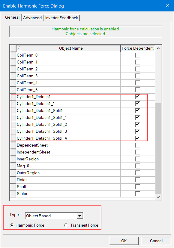
For a Maxwell 2D or 3D transient design, select Maxwell > Enable Harmonic Force Calculation.
-
In the window that opens, select the objects that are force dependent, and make sure the Type is ObjectBased and Harmonic Force is selected.
-
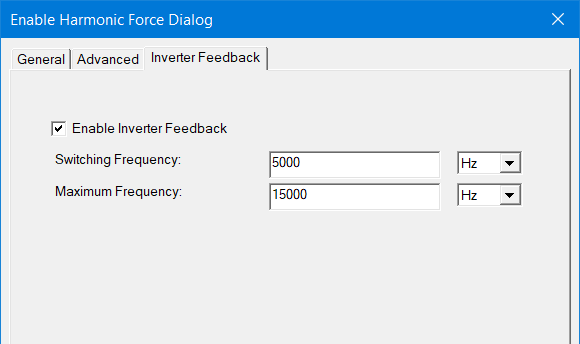
From the Inverter Feedback tab, enable feedback, and specify the switching frequency and the maximum frequency. The switching and maximum frequencies are only available if Enable Inverter Feedback is checked; their default values are 4000 Hz and 8000 Hz, respectively.
-
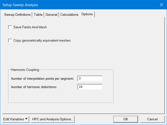
In the Project Manager tree, right-click on the Optimetrics entry and select Add > Parametrics and Designs of Experiments > Parametric to create a parametric analysis. In addition to the desired sweep setup, under the Options tab, specify number of harmonic distortions; the default value is 10.
-
After running the analysis in Maxwell, select Maxwell > Export Transient / Harmonic Force to export harmonic force files to Ansys Workbench:
![]()
Limitations
For this feature, there are some limitations, as explained below.
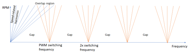
When the machine is excited by an inverter with constant PWM switching frequency, harmonic forces can be categorized into two groups: The frequency of harmonic forces excited directly by the machine are directly proportional to the machine’s speed (speed-related harmonics). In contrast, harmonic forces excited by the inverter feeding are dependent on both the PWM frequency and machine’s speed. This leads to “so-called” forward and backward spectral lines in the frequency-speed plane. This pattern of forward and backward lines occurs around the switching frequency and multiples of it.
The force interpolation method for inverter-fed electrical machines is based on identifying which forces are excited by the machine or by the inverter feeding; different interpolations are used for these two. So when using this feature, keep in mind the following:
-
For the speed-related harmonics, only the first 50 orders are used, and higher frequency data is not used. (This order is based on the number of periods run in the model.)
-
When lines of speed-related harmonics intersect with the harmonic lines from the switching frequency, shown as “Overlap region” in the image above, the interpolation for inverter-excited forces will overwrite the interpolation performed for speed-related harmonics. Thus, the interpolated force will be based on the inverter-excited forces only. This can lead to numerical errors when the region of overlap is significant; for example, when a low switching frequency is used.
-
In the “Gap” region between different components, no interpolated forces are calculated (a small value is assigned for numerical reasons).
-
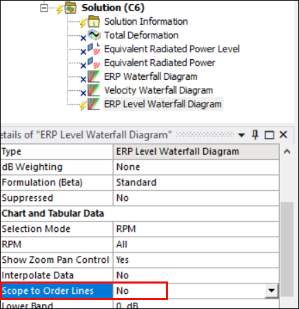
When generating waterfall diagrams in Harmonic Response analysis in Ansys Mechanical, please set Scope to Order Lines to No as this option is only valid for speed-related harmonics.